Figure below shows the circuit diagram of the emitter-follower configuration
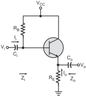
Circuit diagram of emitter-follower configuration
Figure below shows the simplified h-parameter equivalent model for the emitter-follower configuration.
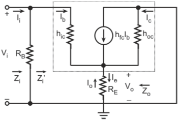
Simplified h-parameter equivalent model for the emitter-follower configuration
Input impedance: Input impedance is determined in a similar manner as that for the emitter-bias configuration with unbypassed emitter resistor. The input impedance looking into the network to the right of resistor RB is given by
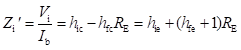
The overall input impedance Zi is given by parallel combination of resistor RB and impedance Zi'.

Output impedance:
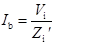
The base current Ib is given by
The emitter current Ie is then given as
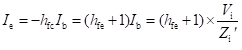
Substituting the value of Zi in the above equation we get

Figure below shows the network defined by the above equation.
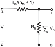
Equivalent network
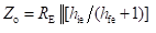
The output impedance Zo is defined by setting the input voltage Vi equal to zero. The output impedance Zo is a parallel combination of resistor RE and impedance defined by hie/(hfe + 1).
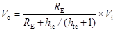
Voltage gain: Output voltage Vo is expressed in terms of the input voltage Vi as
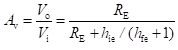
The voltage gain Av is then given by
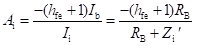
Current gain: The current gain Ai is given by

The output current Io is given by

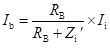
Base current Ib is given by
Therefore, Ai is given by