Differential amplifiers

  • What is a differential amplifier?

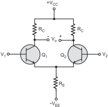
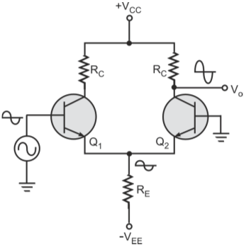
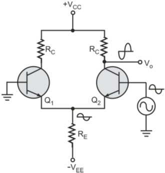
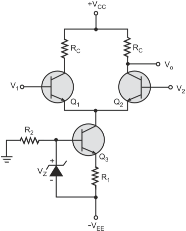
    Differential amplifier is an amplifier whose output is proportional to the difference between the two input signals.

  • Why are differential amplifiers used in the front-end of opamps?

    Differential amplifiers which do not require coupling and emitter bypass capacitors are used for fabricating the front-end circuits of opamps. It is so because it is not practical to fabricate large-value capacitors (larger than 50 pF) on the IC chip. Even large-value resistors are also not easy to fabricate in the IC form. Large-value resistances are simulated by suitable transistor configurations.

  • Why is differential amplifier configuration called a long tail pair?

    The differential amplifier configuration is also called a long tail pair as the two transistors share a common-emitter resistor. The current through this resistor is called the tail current.

  • Draw the configuration of a basic single-stage differential amplifier?

    Figure below shows the basic single-stage differential input–differential output differential amplifier configuration.

    Basic differential amplifier

    In the above figure, base terminal of Q1 is the non-inverting input and base terminal of transistor Q2 is the inverting input. The output is in-phase with the signal applied at non-inverting input and out-of-phase with the signal applied at inverting input and is given by Ad × (V1  V2), where Ad is the differential gain

  • What is the value of tail current in the differential amplifier in Q4?

    For DC analysis, if we ignore the voltage drop across base-emitter junctions of the two transistors, the common-emitter point for all practical purposes is at ground potential. Therefore, the tail current is given by VEE/RE, which is constant. The tail current is divided into two separate paths, one through Q1 and the other through Q2. As the two halves are symmetrical, total current sharing depends upon the voltages applied to the two inputs

  • What is the key parameter of a differential amplifier?

    One of the main parameters of a differential amplifier is common mode rejection ratio (CMRR). It is the ability of a differential amplifier to amplify differential input and its insensitivity to common mode input. It is defined as a ratio of differential gain to common mode gain. Differential gain of differential amplifier in Q4 is RC/re' Where, re' is the dynamic resistance of the base-emitter junctions of the two transistors. Common mode gain of differential amplifier in Q4 is RC/2RE CMRR therefore is given by 2RE/re'

  • Draw the circuit of a single-ended differential amplifier with input applied at the non-inverting input?

    Figure below shows single-ended differential amplifier with input applied at the non-inverting input. The output is taken from the collector of transistor Q2

    Single ended differential amplifier with signal applied to non-inverting input

  • Draw the circuit of a single-ended differential amplifier with input applied at the inverting input?

    Figure below shows single-ended differential amplifier with input applied at the inverting input. The output is taken from the collector of transistor Q2.

    Single ended differential amplifier with signal applied to inverting input

  • Draw a Differential amplifier with a constant current source?

    For a high value of CMRR, the value of RE should be as high as possible. That is why in practical opamp circuits, RE is replaced by a constant current source. Figure below shows a differential amplifier with conventional constant current source in place of resistor RE.

    Differential amplifier with conventional constant current source in place of RE

  • Draw a Differential amplifier with a current mirror?

    A current mirror configuration is also used to implement a constant current source. Figure below shows differential amplifier circuit with a current mirror configuration.

    Differential amplifier with current mirror constant current source in place of RE

    The current mirror works as follows. The diode connected across the base-emitter junction and the base-emitter junction diode of the transistor have matched current-voltage characteristics. In this case, the collector current of the transistor equals the current through resistor R. Therefore, the collector current is a mirror image of the resistor current.

  • Why is current mirror configuration commonly used as current source and active load in IC opamps?

    Current mirror configuration is commonly used as current source and active load in IC opamps as it is very easy to match the current-voltage characteristics of a diode and base-emitter junction diode of a transistor in ICs because of both being on same chip.

  • Draw the circuit of a differential amplifier stage with current mirrors being used instead of emitter resistor RE and collector resistor RC?

    Figure below shows a differential amplifier stage with current mirrors being used instead of emitter resistor RE and collector resistor RC.

    Figure below shows a differential amplifier stage with current mirrors being used instead of emitter resistor RE and collector resistor RC.

  • Draw a simplified internal circuit schematic of a popular opamp 741?

    Figure below shows the simplified internal circuit schematic of the industry standard opamp 741. Transistors Q1 and Q2 constitute the differential amplifier. Transistor Q6 is configured as an emitter-follower buffer stage. Q5 and associated components make the common-emitter stage that feeds the output class-B push–pull stage. The output stage is configured around Q8 and Q9. It has current mirror configuration as active loads and also as the tail resistor of differential amplifier.

Got a voltage spike of curiosity?

Send your doubts now!