Filters

  • What is a filter?

    The filter circuit smoothens the ripple of the rectifier voltage.

  • What is the function of filters in a power supply?

    The ripple content in the rectified waveform is so large that the waveform can hardly be called a DC. The filter in a power supply helps in reducing the ripple content (the amplitude of AC component).

  • List the different types of filters?

    Different types of filters include the following.

    • Inductor filters
    • Capacitor filters
    • Inductor–capacitor combination filters

  • What is an inductor filter?

    An inductor offers high reactance to AC components. This is the basis of filtering provided by inductors. Figure below shows the full-wave rectifier circuit with inductor filter.

    Inductor filter

  • Draw the output waveform for an inductor filter when a full-wave rectified signal is applied at its input?

    The load current waveforms with and without filter are shown in figure below.

    Input and output waveforms for an inductor (or choke) filter

  • Derive the expression for ripple factor (r) for an inductor filter?

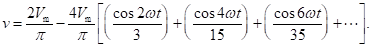
    The Fourier series expansion of a full-wave rectified voltage waveform is given by

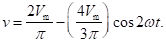
    Neglecting higher order terms beyond second harmonic, the above equation reduces t

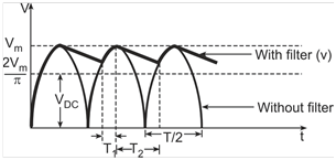
    The first term represents the DC component and the second term represents the AC component.

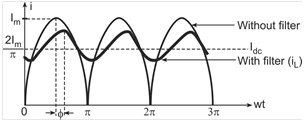
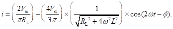
    Since the AC component of current will lag behind the voltage by an angle (∅) given by tan–1(2wL/RL), the expression for resulting current can be written as

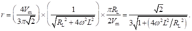
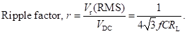
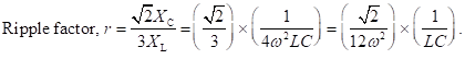
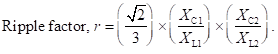
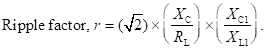
    Ripple factor is the ratio of RMS value of the AC component to that of the DC component. Therefore, it is given by

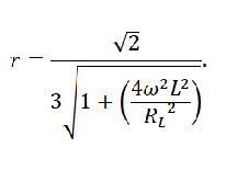
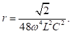
    For (4w2L2/RL2) much greater than 1, expression for ripple factor (r) reduces to

    r equals RL/1333L for power line frequency of 50 Hz and RL/1600L for power line frequency of 60 Hz. (L is inductance in Henries and R is resistance in ohms).

  • Why is choke filter is not effective for light loads?

    Ripple factor for an inductor filter (choke filter) is directly proportional to load resistance (RL). That is, the ripple content increases with increase in load resistance. Therefore, the choke filter is not effective for light loads (or high values of load resistance). It is preferably used for relatively higher load currents.

  • What is the value of ripple factor for a choke filter under no load condition?

    No load condition means that the load resistance is infinite or it is an open circuit. Exact value of ripple factor for an inductor filter is given by

    For no load condition, we get r = √2/3 = 0.471. This value is very close to the value in the case of full-wave rectifier without filter. The slight difference can be attributed to omission of higher order terms in calculation of the ripple factor for the inductor filter.

    Therefore, the presence of inductor filter is as good as not there in the case of load resistance tending to become infinity. In other words, an inductor filter becomes less and less effective with increase in value of load resistance.

  • How does the inductor filter improve over the value of ratio of rectification and TUF as compared to that of a rectifier?

    With inductive filtering, the load current never drops to zero. If the value of inductance is suitably chosen, the flow of current through the diodes and the secondary of the transformer are much more even than it would have been without the filter. This leads to ratio of rectification of almost unity due to RMS and DC values of the filtered current waveform to be almost the same and an improved transformer utilization factor.

  • Draw the circuit of a capacitor filter?

    Capacitor filter is based on the fact that a capacitor offers a low reactance to AC components. Figure below shows a capacitor filter connected across the output of a full-wave rectifier. The AC components are bypassed to ground through the capacitor and only the DC is allowed to go through to the load.

    Capacitive filter

  • Draw the output waveform for a capacitor filter when a full-wave rectified signal is applied at its input?

    The capacitor charges to the peak value of the voltage waveform during the first cycle and as the voltage in the rectified waveform is on the decrease, the capacitor voltage is not able to follow the change as it can discharge only at a rate determined by (CRL) time constant. The capacitor would discharge before the voltage in the rectified waveform exceeds the capacitor voltage thus charging it again to the peak value. The input and the output waveforms for a full-wave rectified input signal is given in figure below. The ripple content is inversely proportional to C and RL.

    Input and output waveforms for a capacitor filter

  • Capacitor filter is effective for which loads?

    The ripple content in a capacitor filter is inversely proportional to C and RL. Ripple can be reduced by increasing C for a given of RL. In the case of light loads (or high values of load resistance), the capacitor would discharge only a little before the voltage in the rectified waveform exceeds the capacitor voltage thus charging it again to the peak value. For heavy loads when RL is small, even a large capacitance value may not be able to provide ripple within acceptable limits. Therefore, capacitor filters are effective for light loads i.e. for high values of load resistance.

  • Compute the ripple factor for a capacitor filter?

    Referring to the waveform of Figure Q11, to a reasonable approximation, the ripple waveform can be considered to be a triangular one. The charge acquired by the filter capacitor during the time it is charging (T1) equals the charge lost by it during the time it is discharging through load resistance RL (T2).

    Equating the two, we get

    In the case of a large CRL, time constant T2 equals T/2 where T is the time period of the AC input. This gives

    Assuming a triangular ripple waveform as outlined earlier,

    Therefore,

    Also,

    IDC = VDC/RL.

    Therefore,

    Ripple factor (r) equals 2887/CRL for power line frequency of 50 Hz and 2406/CRL for a power line frequency of 60 Hz (C is the capacitor in microfarads and RL is the load resistor in ohms).

  • What is the effect of capacitor’s ESR on the ripple factor?

    The value of ripple factor calculated in Q13 is true in the case of an ideal capacitor with a zero equivalent series resistance (ESR). In the case of practical capacitors, the ESR is easily of the order of several ohms or even a few tens of ohms for the large values of capacitance encountered in filter capacitors. In such cases, the ripple factor deteriorates from the computed value. The ESR should also be considered while computing the repetitive peak current during the charging process and also the surge current that would flow when the power is initially is switched on and the filter capacitor is fully discharged.

  • What is the advantage of combined LC filters over inductor filters and capacitor filters?

    An inductance filter is effective only at heavy load currents and a capacitor filter provides adequate filtering only for light loads. The performance of inductor and capacitor filters deteriorates fast as the load resistance is increased in the case of former or decreased in the case of the latter. Apparently, an appropriate combination of L and C filter would provide adequate filtering over a wide range of load resistance RL values

  • Draw the circuit diagram of a LC filter?

    Figure below shows an LC filter connected across the output of a full-wave rectifier.

    LC filter

    If the value of inductance (L) in the LC filter is small, the filter will predominantly be a capacitor filter and the capacitor will repetitively charge to the peak value and cut off the diodes. The current in this case is in the form of short pulses only. An increase in the value of inductance allows the current to flow for longer periods. If the inductance is further increased, we reach a stage where one diode or the other is always conducting with the result that the current and voltage to the input of LC filter are full-wave rectified waveforms. This is known as the critical value of inductance (LC).

    If the inductance (L) is equal to or more than the critical inductance, the voltage applied to the filter and the load can be approximated by the following equation.

  • Calculate the value of ripple factor of a LC filter?

    For a properly designed LC filter, XC << RL and XL >> XC at a radian frequency of 2w. XL therefore primarily determines the AC component of ripple. Therefore,

    Also,

    The above expression proves that the ripple factor in a choke input LC filter is independent of RL. Ripple factor reduces to 1.2/LC for power line frequency of 50 Hz and 0.83/LC for a power line frequency of 60 Hz (L is the inductance in Henries and C is the capacitance in Microfarads).

  • What consideration is important while choosing the value of inductance for the LC filter?

    The chosen value of inductance should be greater than or equal to the critical inductance.

  • What is the value of critical inductance for the LC filter?

    The value of critical inductance is such that the DC value of current is equal to or greater than the negative peak of the AC component to ensure a continuous flow of current. That is,

    This gives,

    Therefore,

    LC equals RL/942 for a power line frequency of 50 Hz and RL/1131 for a power line frequency of 60 Hz (L is the inductance in Henries and C is the capacitance in Microfarads). In practice, LC should be about 25% higher to take care of approximation made in writing expression for v.

  • What is the advantage of multiple section LC filter over a single section LC filter?

    Figure below shows the circuit diagram of a two-section LC filter.

    Two-section LC filter

  • What is the value of ripple factor for a two-section LC filter?

    The value of

    For L1 = L2 = L and C1 = C2 = C,

    Ripple factor equals 3/L2C2 for power line frequency of 50 Hz and 1.45/L2C2 for power line frequency of 60 Hz. (L is the inductance in Henries and C is the capacitance in Microfarads). The value of critical inductance is as it is in the case of single section filter.

  • Draw the circuit diagram of a CLC filter?

    CLC Filter (∏-Filter) is basically a capacitor filter followed by LC section. Figure below shows the CLC filter. The ripple characteristics of this filter are similar to those of two-section LC filter.

    CLC or -type filter

  • Write the expression for ripple factor of a CLC filter?

    Therefore,

  • What is the problem of a CLC filter?

    CLC filter suffers from the problem of high diode peak currents, poor regulation and a ripple that is dependent upon load resistance. In the case of very small load current, one may replace the inductance (L) with a resistance equal in value to the inductive reactance at the ripple frequency of 2w.

Got a voltage spike of curiosity?

Send your doubts now!