a name="author" content="AAROHAN RESEARCH LAB"> High-Frequency Response of Transistor Amplifiers

High-Frequency Response of Transistor Amplifiers

  • Why is the h-parameter model of a transistor not applicable at high frequencies?

    The h-parameter model of a transistor is not applicable at high frequencies because at high frequencies the transistor behaves in quite a different manner to what it does at low frequencies. At low frequencies, it is assumed that the transistor responds to the input voltage and current instantly as the diffusion time of the carriers is very small as compared to the rise time of the input signal. However, at high frequencies this is not the case and hence the h-parameter model is not valid at high frequencies.

  • Which model is used for transistors at high frequencies?

    A commonly used model at high frequencies is the hybrid-π model or the Giacoletto model. It gives a fairly good approximation of the transistor’s behavior at high frequencies.

  • Draw the hybrid-π model for the common-emitter NPN transistor shown in figure below?

    Common-emitter NPN transistor

    Figure below shows the hybrid-π model for the common-emitter NPN transistor shown in figure below.

    High-Frequency Response of Transistor Amplifiers

    The model has the following features.
    • The node B' is an internal node and is not physically accessible.
    • All the components, both capacitive as well as resistive, are assumed to be independent of frequency.
    • These components are dependent on the quiescent operating conditions, but under a given bias condition they do not vary much for small input signal variations.
    • The circuit components are the base-spreading resistance (rbb'), conductance between terminals B' and E (gb'e), conductance between terminals C and E (gce), conductance between terminals B' and C (gb'c), current source between terminals C and E (gmVb'e), collector-junction barrier capacitance (Cc) and diffusion capacitance between terminals B' and C (Ce).
    • Ohmic base-spreading resistance (rbb') is represented as a lump parameter between the external base terminal (B) and the node B'.
    • Conductance (gb'e) takes into account the increase in the recombination base current due to the increase in the minority carriers in the base region.
    • gce is the conductance between the collector and the emitter terminals.
    • Conductance (gb'c) takes into account the feedback effect between the output and the input due to Early effect. (Early effect results in modulation of the width of the base region due to varying collector–emitter voltage which in turn causes a change in the emitter and the collector currents as the slope of the minority-carrier distribution in the base region changes.)
    • Small changes in the value of voltage Vb'e cause excess minority carriers, proportional to the voltage Vb'e, to be injected in to the base region. This results in small-signal collector current. Hence, the magnitude of the collector current for shorted collector and emitter terminals is proportional to the voltage Vb'e. The current generator gmVb'e takes into account this effect.
    • gm is the transconductance of the transistor.
    • Cc is the collector-junction barrier capacitance. This capacitance is split into two parts, namely, the capacitance between C and B' terminals and the capacitance between C and B terminals. The capacitance between C and B terminals is also referred to as the overlap-diode capacitance.

  • Determine the hybrid-2 conductance values?

    Figure below shows the hybrid-π model for a common-emitter transistor amplifier applicable at low frequencies. As the hybrid-π model is drawn for low frequencies, the capacitive elements are considered as open circuit.

    Hybrid-π model for a common-emitter transistor at low frequencies

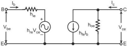
    Figure below shows the h-parameter model for a common-emitter transistor amplifier applicable at low frequencies. Base-Spreading Resistance (rbb): From the h-parameter model, the value of input resistance when the output terminals are shorted, that is Vce = 0, is equal to hie. Under these conditions for the hybrid-π model, the input resistance is given by

    Therefore

    As rb'c >> rb'e, therefore the above equation can be approximated as

    Conductance between Terminals B' and C or the Feedback Conductance (gb'c): For the h-parameter model, if the input terminals are open-circuited, then hre is the reverse voltage gain. In terms of the hybrid-π model, the value of hre is given by

    Therefore

    As the value of hre is in the range of 10–4, that is, hre << 1, therefore the above equation can be approximated by

    or

    The equation also verifies that the value of resistance rb'c is much larger than resistance (rb'e), that is, rb'c >> rb'e. Conductance between Terminals C and E (gce): For the hybrid-π model, if the input terminals are open circuit then

    For h-parameter model, with the input terminals open, that is with Ib = 0, the collector current Ic is given by

    Value of hoe is given by

    Substituting the value of Vb'e we get

    Substituting the value of hre as gb'c/gb'e, 1/rce as gce, 1/rb'c as gb'c and assuming that rb'c >> rb'e, the above equation can be rewritten as

    Value of gm is given by

    Therefore

    Rearranging the terms in the above equation we get

    As the value of hfe >> 1, the above equation can be approximated as

    Conductance between Terminals B' and E or the Input Conductance (gb'e): For the h-parameter model as the value of resistance (rb'c) is much greater than resistance (rb'e), most of the current Ib flows into rb'e and the value of the voltage (Vb'e) is given by

    The short-circuit collector current (Ic) is given by

    Short-circuit current gain (hfe) is defined as

    Therefore,

    Transistor’s Transconductance (gm): Transconductance of a transistor (gm) is defined as the ratio of the change in the value of collector current to change in the value of voltage Vb'e for constant value of collector–emitter voltage. ,br> For a common-emitter transistor configuration, the expression for collector current is given by

    The short-circuit collector current is given by gmVb'e. Therefore, the value of gm is given by

    The partial derivative of the emitter voltage w.r.t. to the emitter current (i.e., aVe/bIe) can be represented as the emitter diode resistance (re). Dynamic resistance of a forward-biased diode (rd) is given as

    Where,
    VT is the volt equivalent of temperature ID is the diode current
    Therefore, the value of gm can be generalized as

    As the value of Ic >> ICO, therefore the value of gm for an NPN transistor is positive. For a PNP transistor, the analysis can be carried out on similar lines and the value of gm in the case of a PNP transistor is also positive. Therefore, the expression for gm can be written as

  • Define the Hybrid-2 Capacitances?

    Hybrid-π model has two capacitances namely the collector-junction barrier capacitance (Cc) and the emitter-junction diffusion capacitance (Ce). Collector-Junction Capacitance (Cc): Capacitance Cc is the output capacitance of the common-base transistor configuration with the input open (IE = 0). It is also specified as Cob. As the collector-base junction is reverse-biased, Cc is the transition capacitance. It varies as VCB–n, where n is 1/2 for abrupt junction and 1/3 for a graded junction. Emitter-Junction Capacitance (Ce): Capacitance Ce is the diffusion capacitance of the forward-biased emitter junction and is proportional

  • How do Hybrid-2 Parameters vary with variation in transistor current and voltage and temperature?

    Hybrid-π parameters vary with change in collector current (IC), collector–emitter voltage (VCE) and temperature (T). Table below lists these variations.

    Variations in the values of hybrid-2 parameters

  • Draw the hybrid-π equivalent model for a common-emitter amplifier with short-circuit load as shown in figure below?

    Common-emitter amplifier with short-circuit load

    Figure below shows the hybrid-π equivalent model for the circuit. The input source is a sinusoidal source and furnishes a sinusoidal input current Ii. The load current produced is IL.

    Hybrid-π equivalent model for Common-emitter amplifier with short-circuit load

    The equivalent model shown in the figure can be simplified to that shown in figure below. The assumptions made in the simplified model are that the conductance gb'c can be neglected as the value of gb'c << gb'e. The conductance gce has also been removed as it is placed across short-circuited terminals. Another approximation is that the current delivered directly to the output through the conductance gb'c and capacitance Cc has been neglected.

    Simplified hybrid-π equivalent model for Common-emitter amplifier with short-circuit load

  • What are the parameters of interest for a common-emitter amplifier with short-circuit load?

    The parameters of interest are the β-cut-off frequency (f'β) and the short-circuit gain bandwidth product (fT). β-cut-off frequency (fβ) is the frequency at which the value of short-circuit common-emitter gain reduces to 0.707 times its mid-band value. In other words, at f', the short-circuit common-emitter current gain is 3 dB below its mid-band value. Thus, fβ represents the maximum attainable current-gain bandwidth for the common-emitter amplifier. The actual maximum bandwidth depends upon the circuit connections. Short-circuit gain bandwidth product (fT) is the frequency at which the short-circuit common-emitter current gain value is unity or 0 dB.

  • Determine the value of β-cut-off frequency?

    From the simplified hybrid-π model circuit shown in Q7, the value of load current (IL) is given by

    The value of Vb'e is given by

    The value of current gain (Ai) under short-circuit condition is

    Therefore,

    Rearranging the terms, we get

    As

    Therefore, the value of current gain Ai is given by

    At zero, low and mid-frequencies, the value of current gain Ai is given by

    Magnitude of current gain (Ai) is given by

    The value of fβ is given by

  • Write the expression for gain-bandwidth product (fT)?

    fT is the frequency at which the magnitude of the short-circuit current gain in the common-emitter amplifier becomes unity. As the value of hfe >> 1, the magnitude of the current gain Ai becomes unity at the frequency given by the product of hfe and fr. Therefore, fT is given by

  • How does gain-bandwidth product (fT) vary with collector current of the transistor?

    fT is a strong function of the collector current of the transistor. The variation of fT with collector current (Ic) is shown in figure below.

    Variation of the frequency fT with collector current

  • How does the short circuit current gain of a common-emitter amplifier varies with frequency?

    Current gain Ai is given by

    Variation of the frequency fT with collector current

  • What is α-cut-off frequency?

    α;-cut-off frequency is the frequency at which the short-circuit current gain value in the common-base configuration drops by 3 dB to its value at low frequencies. It is represented as fβ.

  • Why is the value of fα is much larger than the value of fα;?

    Transistor used in common-base configuration has a much higher value of 3 dB frequency as compared to the transistor used in common-emitter configuration. Therefore, the value of fα is much larger than the value of fα.

  • Write the expression for current gain in common-base configuration?

    Current gain in a common-base configuration is given by

    Where, fα is the α-cut-off frequency

  • Write the relation between fβ and fα?

    The relation between fβ and fα is given by

    Therefore, the bandwidth offered by the common-base amplifier is much higher than that offered by a common-emitter amplifier, although the latter has much higher value of gain.

  • Write the expression for α-cut-off frequency?

    The expression for the α-cut-off frequency is given by

    As the value of hfe α1/(1 + hfb), the above equation can be rewritten as

  • Show the comparative variation of short-circuit current gains for the common-emitter and common-base configurations vary with frequency?

    Figure below shows the comparison of variation of short-circuit current gains for the common-emitter and common-base configurations with frequency.

    Comparison of the variations of short-circuit current gains of common-emitter and common-base configuration with frequency

  • What is Miller’s theorem?

    According to Miller’s theorem, the circuit with feedback impedance can be replaced by an equivalent circuit such that the feedback impedance is split into two impedances: one between the input terminal and the ground (Zin) and the other between the output terminal and the ground (Zout). Let us consider a circuit configuration shown in figure below. As shown in the figure, it comprises three nodes, namely, input node 1, output node 2 and a ground node G. An impedance (Z) is connected between the input and the output nodes. This impedance is referred to as the feedback impedance.

    Circuit configuration with feedback impedance

    This impedance has an effect on the functioning of the circuit. It is very difficult to analyze such a network as the impedance affects the input and the output simultaneously. Miller’s theorem helps to analyze such circuit configurations. Figure below shows the Miller’s equivalent circuit of the network with feedback impedance.

    Miller’s equivalent circuit of the network with feedback impedance

    The impedance on the input side (Zin) is given by

    The impedance Zin appears in parallel with the input terminals of the network. The impedance seen from the output terminals (Zout) is given by

  • Draw the hybrid-π equivalent model for the common-emitter configuration with resistive load as shown in figure below?

    Circuit diagram of common-emitter configuration with load resistance (RL)

    Figure below shows the hybrid-π equivalent model for the common-emitter configuration with resistive load.

    Hybrid-π equivalent model of common-emitter configuration with load resistance

  • Draw the simplified hybrid-π models making use of Miller’s theorem for common-emitter configuration with load resistance?

    Conductance gb'c can be replaced by its Miller’s equivalent components. The conductance component due to gb'c on the input side is given by gb'c (1 – K), where K = Vce/Vb'e. The value of K is equal to 'gmRL. The conductance component due to gb'c on the output side is given by gb'c [(K – 1)/K]. The Miller’s component of the capacitance Cc on the input side is given by Cc (1 – K) and on the output side is given by Cc [(K – 1)/K]. Figure below shows the equivalent circuit with components gb'c and Cc being replaced by their Miller’s equivalent components.

    Simplified hybrid-π model making use of Miller’s theorem for common-emitter configuration with load resistance

    As the value of K >> 1, therefore the value of [(K – 1)/K] ≅ 1. Therefore, gb≅c [(K – 1)/K] ≅ gb≅c and Cc [(K – 1)/K] ≅ Cc. The total load resistance RL ≅ is given by

    In most cases, the value of gbc << gce (rb≅c  4–5 M and rce ≅ 80–100 k), therefore gbc can be ignored from the output section. The value of load resistor RL is in the range of 2–5 k ohm. Therefore, the conductance gce can be neglected as compared to 1/RL. Therefore, resistor RL≅ RL. The input conductance (gi) is given by

    Further Simplified hybrid-π model for common-emitter configuration with load resistance

  • Explain the time constants associated with the simplified hybrid-π model in Q20?

    he circuit has two time constants, one associated with the input section and the other associated with the output section. The output time constant (toc) is given by

    The input time constant (tic) is given by

  • . Determine the upper 3 dB frequency with the simplified hybrid-π model in Q20?

    .In practical situations, the output time constant is negligible as compared to the input time constant and hence can be ignored. It may be mentioned here that if the transistor works into a highly capacitive load, then the output time constant will also be predominant and cannot be ignored. The upper 3 dB frequency with neglecting output time constant is given by

    The above equation has been derived by neglecting the effect of the source resistance (Rs). The value of source resistor has a very strong influence on the upper cut-off frequency. The cut-off frequency taking into account Rs and base-spreading resistor rbb is given by

    When the effect of biasing resistors is taken into account, the term Rs in the above equation is replaced by Rs, where Rs is a parallel combination of Rs and biasing resistors.

  • Draw the hybrid-π equivalent model for the common-collector amplifier shown in figure below? (Please note that Capacitance CL is included in parallel with the load resistor RL as the common-collector transistor due to its low output resistance is often used to drive capacitive loads)

    Common-collector amplifier

    Figure below shows the hybrid-π equivalent model for the common-collector amplifier.

    Hybrid-π equivalent model of the common-collector amplifier

  • Apply Miller’s theorem to hybrid-π equivalent model for the common-collector amplifier shown in Q23?

    Applying Miller’s theorem to the hybrid-π equivalent circuit of Q23, we get the equivalent circuit as shown in figure below.

    Simplified hybrid-π equivalent model of the common-collector amplifier employing Miller’s theorem

    Parameter K is given by the ratio of voltages Vec and Vbc.

  • Determine the time constants for the common-collector amplifier shown in Q23 based on the simplified hybrid-π equivalent model in Q24?

    The input time constant tic is given by

    As the low-frequency gain of the emitter–follower configuration is approximately equal to unity, therefore (1 – K) ≅ 0. Therefore, the expression for tic can be approximated by

    The output time constant (toc) is given by

    As the value of (K – 1) ≅ 0, the above equation can be simplified as

    As the output load is highly capacitive, therefore the value of CL >> Cc. Hence,

    This implies that the value of output time constant (toc) is much larger than the input time constant (tic). Hence the upper 3 dB frequency is determined mostly by the output circuit alone.

  • Determine the 3-db cut off frequency and the unity gain bandwidth for the common-collector amplifier shown in Q23 based on the simplified hybrid-π equivalent model in Q24?

    Let the 3-dB upper cut-off frequency be denoted by fH and the unity gain bandwidth be denoted by fT. The value of voltage Vec is given by

    Rearranging the terms, we get

    The value of Vb'e is given by Vb'e = Vb'c – Vec. Therefore, above equation can be rewritten as

    As K = Vec/Vbc, therefore the expression for K is given by

    Multiplying and dividing the above equation by (1 + gmRL) we get

    The above equation can be rewritten as

    Where,
    fH = (1 + gmRL)/2πCLRL The value of fH can be expressed as

    The value of unity gain bandwidth (fT) is given by

    As the value of Ce for a transistor is much larger than Cc, therefore fT can be approximated by

    fT and fH are related to each other by the following equation

    Since the input impedance between terminals B and C is much large as compared to (Rs + rbb), therefore K is approximately the overall voltage gain (AVS), that is,

Got a voltage spike of curiosity?

Send your doubts now!