Low-Frequency Response of Amplifiers

  • Determine the lower cut-off frequency of the voltage-divider BJT amplifier configuration shown in figure below?

    Voltage-divider BJT amplifier configuration
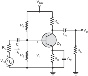
    The various capacitors which effect the response of the voltage-divider BJT amplifier configuration in the low-frequency region are as follows.
    Effect of Input Coupling Capacitor: Ci is the input-coupling capacitor and is connected between the applied input source and the active device. The capacitor Ci forms an RC network as shown in figure below.
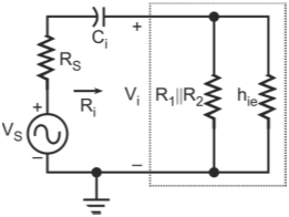
    Determining the effect of input-coupling capacitor on the low-frequency response

    Ri is the input resistance of the amplifier as seen by the source and is given by parallel combination of R1, R2 and hie.

    The voltage Vi applied to the input of the active device is calculated by using the voltage-divider rule. Therefore, voltage Vi is given by
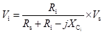
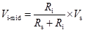
    At mid- and high frequencies the reactance of capacitors Ci and Co will be sufficiently small to permit a short-circuit approximation. Therefore, the input voltage at mid-band frequencies (Vi-mid) is given by
    The cut-off frequency established by the capacitor Ci is given by
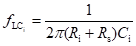
    At fLCi the voltage Vi will be 0.707 times the voltage Vi-mid assuming that Ci is the only capacitive element effecting the low-frequency response. Effect of the Output-Coupling Capacitor: Co is the output-coupling capacitor and is connected between the output of the active device and the active load. Figure below shows the simplified configuration highlighting the effect of Co on the low-frequency response of the amplifier.
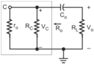
    Determining the effect of output-coupling capacitor on the low-frequency response

    Ro is the total output resistance and is given by

    The cut-off frequency as established by Co is given by

    The output voltage Vo will be 70.7% of its mid-band value at the frequency fLCo assuming that Co is the only capacitive element controlling the low-frequency response. Effect of Bypass Capacitor: Figure below shows the network as seen by the bypass capacitor CE.
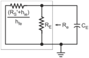
    Determining the effect of bypass capacitor on the low-frequency response

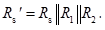
    The value of the equivalent resistance Re is given by

    where,
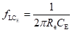
    The cut-off frequency as established by resistance Re and capacitor CE is given by
  • What is the effect of the coupling and bypass capacitors in the mid-band frequency range?

    The input- and the output-coupling capacitors and the bypass capacitors affect only the low-frequency response. At the mid-band frequency range, they are considered as short-circuit equivalent and do not affect the gain at these frequencies.

  • What is the overall lower cut-off frequency of the amplifier?

    If the lower cut-off frequencies offered by the different capacitors are far apart, then the highest cut-off frequency due to the capacitors essentially determines the lower cut-off frequency of the entire system. If the individual lower cut-off frequencies are near to each other, then the effect will be to raise the lower cut-off frequency of the entire system, that is, there is an interaction between the capacitive elements resulting in increased overall lower cut-off frequency for the entire system.

  • Which components effect the low-frequency response of FET amplifiers?

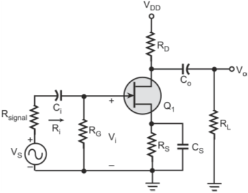
    In the case of FET amplifiers also, there are three capacitors that affect the low-frequency response, namely, the coupling capacitor Ci between the source and the FET, the coupling capacitor Co between the active device and the load and the source capacitor CS.

  • Determine the lower cut-off frequency of the JFET-based amplifier shown in figure below?

    JFET-based amplifier

    The lower cut-off frequencies due to coupling and the source capacitors is given below. Effect of Input-Coupling Capacitor: Figure below shows the equivalent network seen by the input-coupling capacitor Ci.

    Determining the effect of input-coupling capacitor on the low-frequency response

    The cut-off frequency as determined by the capacitor Ci is given by

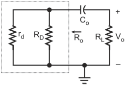
    In most of the applications, the value of resistor RG is much larger than the value of the resistor Rsignal. Therefore, the low-cut off frequency (fLCi) is primarily determined by the values of resistor RG and capacitor Ci. Effect of Output-Coupling Capacitor: Figure below shows the network as seen by the output-coupling capacitor.

    Determining the effect of output-coupling capacitor on low-frequency response

    The output resistance (Ro) is determined by

    The resulting cut-off frequency fLCo is given by

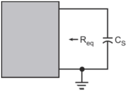
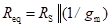
    Effect of Source Capacitor: The equivalent network seen by the source capacitor CS is shown in figure below.

    Determining the effect of source capacitor on the low-frequency response

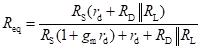
    The equivalent resistance as seen by the capacitor CS is given by

    As the value of resistance rd is very large, assuming rd =∞ we get

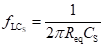
    The cut-off frequency due to the capacitor CS is defined as

Got a voltage spike of curiosity?

Send your doubts now!