Phase Shifters

  • Draw the circuit diagram of a single opamp-based lagging-type phase shifter?

    Figure below shows the circuit diagram of single opamp-based lagging-type phase shifter circuit
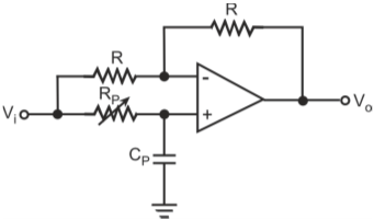
    Lagging-type phase shifter

    The output lags the input by an angle (θ) given by θ (in degrees) = -2 tan–1 (ωRPCP)
    Where, ω= 2πf, f being the frequency of the input signal
    The phase of the input signal can be varied over a wide range by varying RP with 0° and –180° being the extremes. For RP << 1/ωCP, the phase shift is near zero. (It will be 0° when RP = 0 which is not practical). For RP >> 1/ωCP, θ approaches –180° (θ = –180° only for RP = infinity which is again not feasible.) For RP = 1/ωCP, θ = –90°.

  • Draw the circuit diagram of a opamp-based 360-degree lagging-type phase shifter?

    Two lagging-type phase shifters of Q1 can be used in cascade to vary the phase shift over full 360°. Figure below shows the circuit diagram.

    360-degree lagging-type phase shifter

  • Draw the circuit diagram of a lead-type phase shifter?

    Figure below shows the circuit diagram of lead-type phase shifter. As we can see from the figure, it is same as lagging-type phase shifter of Q1 except that the positions of RP and CP are interchanged.

    Lead-type phase shifter

    The phase difference (θ) is given by θ (in degrees) = 2 tan–1 (ωRPCP) The phase of the input signal can be varied over a wide range by varying RP with 0° and 180° being the extremes. For RP << 1/ωCP, the phase shift is near zero. (It will be 0° when RP = 0 which is not practical). For RP >> 1/ωCP, θ approaches180° (θ = 180° only for RP = infinity which is again not feasible.) For RP = 1/ωCP, θ = 90°.

  • How can we make an opamp-based 360-degree lead-type phase shifter?

    Cascade arrangement of two lead-type filter stages can be used for varying phase shift over full 360°.

Got a voltage spike of curiosity?

Send your doubts now!