Summing Amplifier

  • What is a summing amplifier?

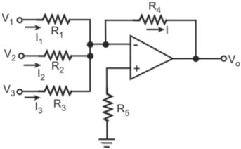
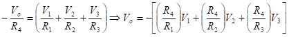
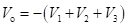
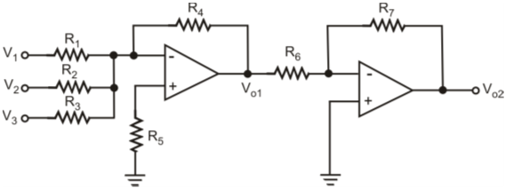
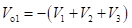
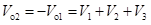
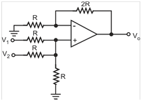
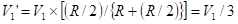
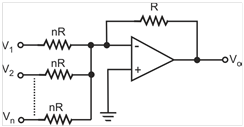
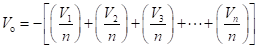
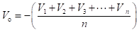
    Summing amplifier produces an output that is equal to the sum of input signals multiplied by corresponding voltage gain values. There are two types of summing amplifiers - inverting summing amplifier and non-inverting summing amplifier.

  • What is an adder circuit?

    Adder circuit is one where the output that is equal to the sum of input signals. Here, voltage gain being unity for all input signals. There are two types of adder circuits - inverting adder and non-inverting adder.

  • Draw the circuit of an inverting summing amplifier?

    Figure below shows circuit diagram of three input inverting-type summing amplifier.

    Inverting-type summing amplifier

    The output voltage is given by

  • Derive the expression for output voltage of an inverting summing amplifier of Q3?

    The expression for output voltage is derived as follows.

    Also

    Therefore

  • What is an inverting adder circuit?

    If in the inverting summing amplifier of Q3, , then it becomes an inverting adder circuit. The output here is given by

  • Draw the circuit of a non-inverting summing amplifier?

    Figure below shows circuit diagram of three input non-inverting summing amplifier.

    Non-inverting summing amplifier

    As we can see from the figure, the non-inverting summing amplifier is constructed from its inverting counterpart by cascading it with an inverting amplifier.

  • What is a non-inverting adder circuit

    If in the non-inverting summing amplifier of Q6, R1 = R2 = R3 = R4 = R and R6 = R7 = R12, then it becomes a non-inverting adder circuit. The output voltage is given by

    An alternative non-inverting adder circuit with two inputs, with a single opamp is shown in figure below. The circuit behaves like a non-inverting amplifier with a gain of 1 to both the inputs.

    Non-inverting adder with single opamp

    With only V1 present and V2 grounded, voltage V1 at non-inverting input is given by

    This voltage gets amplified by a gain factor (1 + 2R/R) = 3 to produce V1 at the output. Similarly, with V1 grounded, V2 also appears as V2 at the output. When both are simultaneously present, output is V1 + V2. That is,

    If the adder circuit of single opamp were to be used for adding n inputs, the feedback resistor value would be equal to nR.

  • What is an averager circuit?

    An averager circuit produces an output that is equal to average of the amplitudes of the applied input signals. Figure below shows an inverting averager circuit for n inputs.

    Inverting averager circuit

    With only one input present at a time and all other inputs grounded, the gain value is 1/n. That is, each input is multiplied by a gain value equal to 1/n. When all the inputs are present simultaneously, the output is given by

    A non-inverting averager may be built by connecting a unity gain inverting amplifier at the output of the inverting averager circuit.

Got a voltage spike of curiosity?

Send your doubts now!