Photoconductors

  • What are photoconductors?

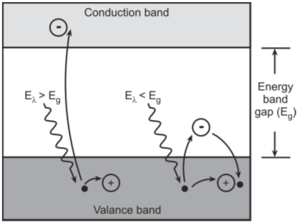
    Photoconductors are semiconductor photosensors whose resistance decreases with increasing incident light intensity. They are bulk semiconductor devices with no PN junction

  • What are other names for photoconductors?

    Photoconductors are also referred to as photoresistors, light-dependent resistors (LDRs) and photocells.

  • Draw the structure of a photoconductor and explain its operation?

    The structure of a photoconductor is shown in figure below. When light is incident on the photoconductor, electrons jump from the valence band to the conduction band. Hence, the resistance of the semiconductor material decreases

    Structure of a photoconductor

  • Draw the circuit symbol of a photoconductor?

    Figure below shows the circuit symbol of a photoconductor.

    Circuit symbol of a photoconductor

  • Explain the characteristic features of a photoconductor?

    Some of the characteristic features of a photoconductor are as follows.
    • Resistance change in a photoconductor is of the order of 6 decades, ranging from few tens of Mega-ohms under dark conditions to few tens or hundreds of ohms under bright light conditions.
    • Wide dynamic response
    • Wide spectral coverage from ultraviolet to far infrared
    • Low cost
    • Slow response time of the order of hundreds of milliseconds

  • Express the resistance-illumination relation in a photoconductor?

    Resistance–illuminance relation in photoconductors is described by

    Where,
    Ra is the resistance at illumination level of Ea Rb is the resistances at illumination level of Eb Ea and Eb are the illumination levels in lux or foot-candles α is the characteristic slope of the resistance–illumination curve. (α is in the range of 0.55 to 0.9)

  • Draw a typical resistance–illumination curve of a photoconductor.

    Figure below shows the resistance-illumination curve of a photoconductor.

    Typical resistance–illumination curve of a photoconductor

  • What are the commonly used semiconductor materials for fabricating photoconductors?

    Commonly used materials in photoconductors are cadmium sulphide (CdS), lead sulphide (PbS), lead selenide (PbSe), mercury cadmium telluride (HgCdTe) and germanium copper (Ge:Cu).

  • Draw the spectral response of photoconductors?

    Spectral response of some of the photoconductor materials is shown in figure below.

    Spectral response of commonly used photoconductor materials

  • What are the typical applications of photoconductors?

    Photoconductors are usually used for detection of infrared radiation. Inexpensive photoconductors like CdS photoconductors are used in many consumer items like camera light meters, clock radios, security alarms, street lights and so on. On the other hand, Ge:Cu cells are used for infrared astronomy and infrared spectroscopy applications.

  • How are photoconductors classified?

    Depending upon whether an external dopant has been added or not to the semiconductor material, photoconductors are further classified as
    • Intrinsic photoconductors
    • Extrinsic photoconductors
    Intrinsic photoconductors: They do not have an external dopant and operate at shorter wavelengths as the electrons have to jump from the valence to the conduction band.
    Extrinsic photoconductors: They have external dopant assed to them and have spectral response covering longer wavelengths.

  • What is the main challenge while designing application circuits using photoconductors?

    When a bias is applied to the photoconductor in the absence of radiation, a current is generated that can be referred to as the dark current. When light is incident on the photoconductor, its resistance decreases and the current flowing through it increases. Photosignal is the increase in the current caused by radiation. Generally, this photosignal is much smaller (of the order of few parts in thousand) than the dark current. Extracting this small signal from the dark current is the primary task of the front-end circuit.

  • Draw simple circuits using photoconductors?

    Figure below shows one possible simple circuit. In this circuit, higher the value of R, higher is the output voltage but the relative responsivity is poorer.

    One possible simple circuit using photoconductor Figure below shows another possible simple circuit using photoconductors.

    Figure below shows one possible simple circuit. In this circuit, higher the value of R, higher is the output voltage but the relative responsivity is poorer.

    Another possible simple circuit using photoconductor

    In this circuit, higher the value of R, lower is the output voltage but the relative responsivity is better.

  • What is the main disadvantage of the circuits shown in Q13?

    In the circuits of Q13, the responsivity of the photoconductor is reduced as the relative change in the circuit resistance is smaller because of the load resistance R. The choice of R and Rsen also affects the output voltage from the circuit.

  • Design a photoconductor circuit which removes the disadvantages of the circuit in Q13?

    Figure below shows the circuit which removes the disadvantages of the circuit in Q13.

    Application circuit of photoconductor using op-amp in the transimpedance mode

    The circuit above provides both better responsivity and high output voltage. It employs the op-amp in the transimpedance mode. The non-inverting input of the op-amp is connected to ground through resistance Rcom to minimize the DC offset voltage.
    The gain of the transimpedance amplifier should be so set that the amplifier does not saturate at the maximum expected radiation intensity.
    The signal voltage can be obtained by subtracting the output voltage in dark condition from the voltage signal and is given by

    Where,
    Rdark is the resistance value of the photoconductor in the absence of radiation

  • What is the disadvantage of the circuit in Q15?

    Dark resistance of the photoconductor is a strong function of temperature and even a slight increase in temperature decreases the value of dark resistance by a large amount and vice-versa. So, the detector temperature has to be controlled to the order of 0.01 °C or better, which is often not feasible. This is the main disadvantage of the circuit in Q15.

  • Design a photoconductor circuit which removes the problem of variation of dark resistance of the photoconductor with temperature?

    The problem can be removed by modulating the incident radiation at a specific frequency, either by placing a mechanical chopper in front of the detector or by electrically modulating the radiation source. The signal generated due to radiation is now an AC signal while the dark current is a DC signal. The AC signal can be separated from the DC background signal using an AC coupled amplifier. Figure below shows a AC coupled voltage mode amplifier.

    Application circuit of photoconductor using voltage mode amplifier with AC coupling

Got a voltage spike of curiosity?

Send your doubts now!