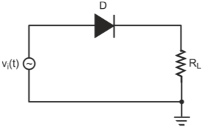
Perform the load line analysis for this circuit.
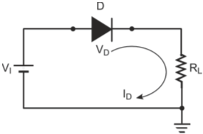
Simple diode circuit with DC input voltage
Applying Kirchhoff’s voltage law to the circuit, we get
Where,
VD is the diode voltage
ID the diode current
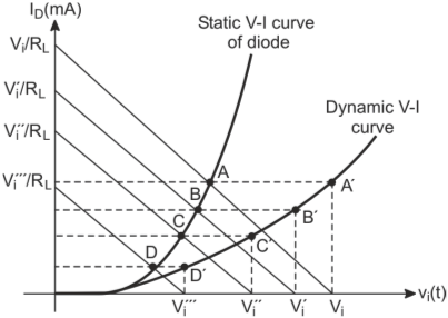
The straight line represented by the above equation is called the load line. The two variables, VD and ID, are the same as the diode’s V-I characteristic axis variables. Therefore, a second relationship between the two variables is given by the V-I characteristic curve of the diode. The intersection of the load line with the V-I characteristic curve of the diode determines the operating point of the circuit also called the quiescent point or the Q-point.
The load line can be drawn by determining its intercepts on the voltage and the current axis. For VD = 0, ID = VI/R and for ID = 0, VD = VI. The straight line joining these two points is the load line. The slope of the load line is given by –1/RL. Figure below shows the load line analysis for a diode circuit for DC input voltage. The operating point for the circuit is (VDQ, IDQ), where VDQ = VDD – IDQ RL.
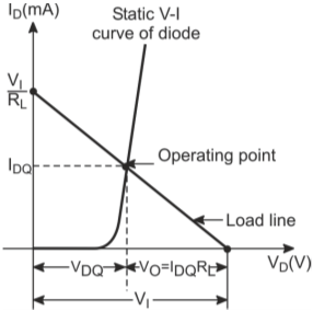
Load-line analysis of a diode circuit for DC input voltage