Armstrong Oscillators

  • What are Armstrong oscillators?

    Armstrong oscillators, also known as Meissner oscillators, use magnetic coupling as means of feeding part of output signal back to input to provide oscillations.

    It is also called a Tickler oscillator due to use of magnetic coupling between the tickler coil and the coupling coil. Tickler coil is the name given to a small coil connected in series with the plate circuit of a vacuum tube and coupled inductively to the grid circuit to provide feedback. In the case of a bipolar junction transistor or an FET, the tickler coil is placed in series with collector or drain circuit and is inductively coupled to the base or gate circuit. A capacitor is placed across either the tickler coil or the coupling coil to form a tank circuit that decides the operating frequency. Figures show the basic circuit arrangements in the two cases with n-channel junction FET used as the active device. Biasing components are omitted for the sake of simplicity.

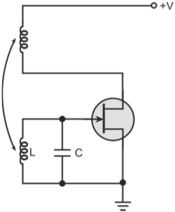
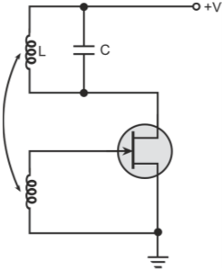
    Basic Armstrong oscillator configurations with capacitor across the (a) coupling coil (b) tickler coil

  • What is the frequency of oscillation of Armstrong oscillators?

    The frequency of oscillation is primarily determined by the tank circuit and is given by

    Where,

    L is the inductance of the coupling coil or that of tickler coil

  • Why is the practical frequency of oscillations slightly different from the one computed in Q2?

    In practice, the frequency of oscillations is slightly different from the theoretical value calculated in Q45 because of stray capacitances, loading of tank circuit, etc.

  • What is the minimum value of gain required to start oscillations in an Armstrong oscillator?

    Minimum gain required to start oscillations is reciprocal of the feedback factor. Feedback factor in this case is given by ratio of mutual inductance between the two coils to the inductance in the tank circuit.

  • Draw the circuit diagram of a shunt-fed Armstrong oscillator configured around a BJT?

    Figure below shows the circuit schematic of shunt-fed Armstrong oscillator configured around a bipolar transistor.

    Shunt-fed Armstrong oscillator configured around a BJT

    The BJT is wired in common-emitter configuration and thus provides a phase shift of 180째. Another 180째 phase shift is provided by magnetic coupling as indicated by placement of dots. Operating frequency is decided by tank circuit comprising capacitor C and inductance L of transformer primary.

  • Draw the circuit diagram of a series-fed Armstrong oscillator configured around a BJT?

    Figure below shows the circuit schematic of series-fed Armstrong oscillator configured around a bipolar transistor.

    Series-fed Armstrong oscillator configured around a BJT

Got a voltage spike of curiosity?

Send your doubts now!