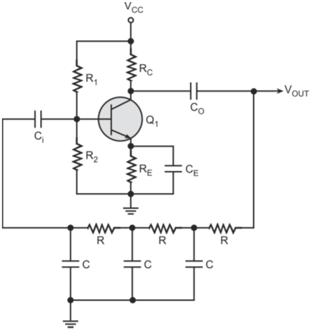
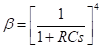
The transfer function of a single-stage lag-type RC network is given by
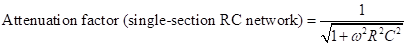
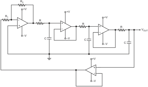
Assuming that the RC sections in the cascade arrangement are independent of each other, that is, individual RC sections do not load each other, then the transfer function of the cascade arrangement of three sections is given by
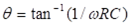
Now, the single-section RC network provides a phase shift (Ø) given by
Therefore,
If this single RC section were to provide the desired phase shift of 60 ° so as to produce a total phase shift of 180 °from the feedback network, then the operational frequency of the oscillator would be given by
Therefore,
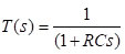
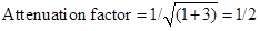
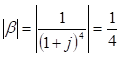
Attenuation factor provided by single-section RC network at this frequency is given by
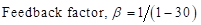
The overall attenuation factor (β) of the feedback network is then given by
β = (1/2)3 = 1/8
Therefore, the amplifier gain must at least be equal to 8.
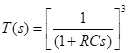
In practice, the required gain is much higher than 8 and also that the oscillation frequency is also higher than
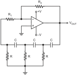
This is due to the loading effect of different RC sections, as explained below, when they are in cascade arrangement.
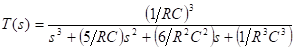
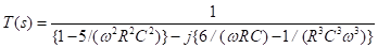
Considering the loading effect, the transfer function of the three-section RC network of the lag type is given by
Substituting
we get
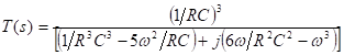
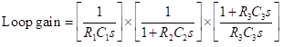
Multiplying both numerator and denominator by R3C3, we get
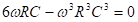
If the feedback network were to provide an overall phase shift of 180 °, then the imaginary part should be equal to zero.
That is,
, which gives
Substituting this value of w, we get the expression for the feedback factor as
To summarize, in the case of a lag-type RC phase shift oscillator, the frequency of oscillation is given by f = [ √6/(2ΠRC)] and minimum amplifier gain is 29.