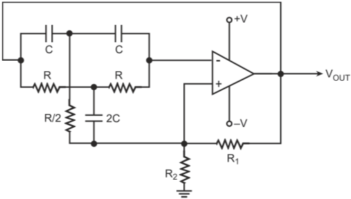
Twin-T network is a parallel connection of a lag-type
T-network (lower T-network in figure of Q28) and a lead-type T-network
(upper T-network in figure of Q28). The lag-type T-network causes the magnitude
of transfer function to fall and the lagging phase shift angle to increase with increase
in frequency. On the other hand, the lead-type T-network causes the magnitude of
transfer function to increase and the leading phase shift angle to decrease with increase
in frequency.
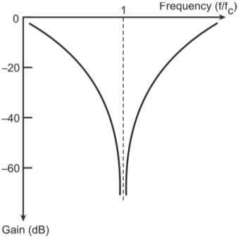
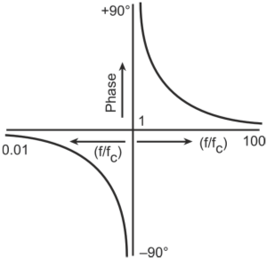
At ɷ = 1/RC, the two T-networks counter-balance each other with the result that both the magnitude as well as the phase of the transfer function tend to become zero. Also, while lagging
phase angle tends to become -90o, the leading phase angle tends
to become +90o. Figure below shows the amplitude and phase response
of the twin-T network as a function of normalized frequency.
Oscillation frequency ɷc equals 1/RC.
(a)
(b)
(a) Magnitude; (b) phase response of twin-T network
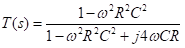
The magnitude of T(s) is
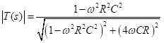
The phase angle of T(s) is
Substituting ɷ = 1/RC in the above equation, we get the magnitude of transfer
function as zero and the phase angle as either -90o or +90o. Zero amplitude for the transfer function implies zero negative feedback at ɷ = 1/RC. At all
other frequencies, there will be very high negative feedback thus allowing the circuit to oscillate only very close to the notch frequency.