SCR and TRIAC Applications

  • List some applications of SCRs?

    SCRs are used in pulse generators, bistable multi-vibrators, half-wave controlled rectifiers, full-wave controlled rectifiers and crowbar protection.

  • Explain the circuit of a pulse generator using an SCR?

    Figure below shows the use of an SCR in a pulse generator circuit.

    SCR-based pulse generator

    In the normal state, the output voltage is at ground level as the capacitor C1 is charged to V volts. The break-over voltage of the SCR used in the circuit must be greater than the voltage V. When a trigger pulse is applied at the gate of the SCR, it fires and the voltage across SCR tends to change abruptly to VH from V changing by V -VH. Capacitor C1 discharges through the ON resistance (r) of the SCR and resistance R1. Generally, r < R1, therefore the discharging time constant is R1C1. The capacitor discharges only upto a voltage VH (called holding voltage). This is so because beyond that holding current of the SCR can no longer be supplied and the SCR turns-OFF.
    Since, voltage across a capacitor cannot change abruptly, the output voltage (VO) changes abruptly from 0 to –(V - VH) and then rises exponentially as C1 discharges. The output abruptly goes to zero when voltage across C1 has decayed to VH which can no longer supply the holding current (IH). The output pulse-width in this case is about 3R1C1.

  • Draw and explain the circuit of bistable multi-vibrator configured around an SCR?

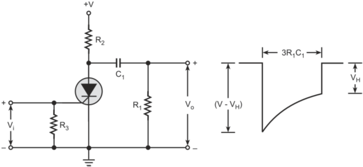
    zFigure below shows the basic circuit arrangement of a bistable multi-vibrator using SCRs.

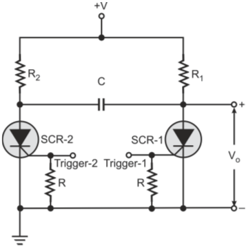
    SCR-based bistable multi-vibrator

    The circuit can be used as a bistable multi-vibrator if the supply voltage is less than the break-over voltage of the SCRs.
    Assume that SCR-1 is initially conducting and SCR-2 is in cut-off. Under these conditions, the current flowing through SCR-1 is limited by R1 only and the output voltage is low (= VH). R1 is chosen in such a way that current through SCR-1 is only slightly greater than the holding current. If we apply a positive trigger at the gate of SCR-2, it starts conducting and the anode voltage of SCR-2 drops from V to VH. This abrupt change is transmitted to the anode of SCR-1 as voltage across C cannot change instantaneously. This negative-going step at SCR-1 anode, turns it OFF. Also, the current that flows through C as a result of SCR-2 anode going to an almost zero potential has to be supplied through R1. R1 cannot supply both the holding current for SCR-1 as well as current through C. As a result, current through SCR-1 falls below its holding current value and is turned-OFF. As SCR-1 goes to OFF-state, output goes high (= V). A positive trigger at SCR-1 gate again changes state.

  • Refer to question 3. What happens if the supply voltage is greater than the break-over voltage of the SCR?

    If the supply voltage is greater than the break-over voltage of the SCR, it becomes an astable multi-vibrator with the frequency of oscillation determined by R1, R2 and C.

  • Draw the circuit diagram of a half-wave controlled rectifier and explain its operation?

    Circuit diagram of a SCR based half-wave controlled rectifier is shown in figure below. During the positive half cycle of the AC source, circuit in the box labelled ‘phase control’, controls the point at which the gate-trigger pulse is applied to the SCR gate. During the negative half cycle, SCR remains reverse-biased and there is no current through the load. Therefore, input AC power appears across the load only during the conduction period of the SCR. The AC power in the load thus can be controlled by controlling the firing angle of SCR. The firing angle can be anywhere between 0º and 180º.

    Figure below shows the waveform appearing across the load.

    Figure below shows the SCR anode waveform.

    SCR anode waveform

  • Explain the circuit of a SCR-based full-wave controlled rectifier?

    Figure below shows the circuit of a SCR based full-wave controlled rectifier.

    SCR based full-wave controlled rectifier

    Conduction angle is 90º. Diodes D1 and D3 conduct during positive half cycles of input whereas diodes D2 and D4 conduct during negative half cycles of input. The power control is provided by SCR. Figure below shows the input and output waveforms.

    Relevant waveforms in full-wave controlled rectifier

  • Draw and explain the SCR-based crowbar protection circuits?

    An SCR-based crowbar circuit protects the output voltage of a power supply from becoming excessively high. Figure below shows the SCR-based crowbar protection circuit.

    SCR-based crowbar protection circuit

    The over-voltage at which crowbar action occurs is given by (VZ + VGT). VZ is selected to be higher than the normal operating voltage of the power supply. The crowbar circuit remains inactive as long as the power supply output voltage is less than (VZ + VGT). If the output voltage exceeds (VZ + VGT), SCR is triggered. It shorts the load, thus protecting the load from excessive voltage. Crowbar is always used in conjunction with a fuse or some kind of current limiting to protect the power supply.

  • What is the most important parameter of a crowbar circuit?

    Turn-ON time is an important parameter of a crowbar circuit. SCRs with turn-ON time as fast as a microsecond suit the application

  • What is the disadvantage of the basic SCR crowbar circuit of question

    The turn-on of SCR in the circuit above is dependent on the breakdown of the Zener diode. Owing to a slightly curved knee at the breakdown point in the Zener V-I characteristics, the device becomes a bit sluggish. Therefore, the response of the crowbar circuit is sluggish.

  • How the problem of sluggish response of a basic crowbar circuit can be overcome?

    The problem of sluggish response of the basic crowbar circuit is overcome by adding gain to the trigger circuit of SCR as shown in the figure below.
    Crowbar action occurs at an output voltage given by

    Modified SCR crowbar circuit

  • Draw the circuit and explain the operation of TRIAC-based AC power control?

    Figure below shows the circuit of TRIAC-based AC power control circuit. Here the phase angle is being controlled by a DIAC. During both positive and negative half cycles, the TRIAC conducts as and when the break-over voltage of the DIAC is exceeded.
    The TRIAC turns-OFF when the current falls below its holding value. Another trigger during the negative half cycle turns the TRIAC on again. The period for which the TRIAC conducts during positive and negative half cycles of AC input can be controlled by varying R. By controlling time constant (RC), we can control the time instant at which DIAC would fire which in turn triggers the TRIAC.

    TRIAC-based AC power control

Got a voltage spike of curiosity?

Send your doubts now!