Bias Compensation

  • In which applications is bias compensation used?

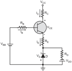
    The biasing techniques offer stability to the operating point (ICQ, VCEQ) by virtue of negative feedback but they also reduce the gain of the circuit. In applications where the reduction in gain is not acceptable, compensation techniques are used to arrest the variation in the operating point.

  • What are the different bias compensation techniques?

    Bias compensation techniques make use of temperature-sensitive devices such as diodes, thermistors, transistors, sensitors etc. to compensate for the changes in the operating point caused due to changes in temperature. Commonly used compensation circuits include the following

    • Diode Compensation for Base-Emitter Voltage (VBE)
    • Diode Compensation for Leakage Current (ICO)
    • Thermistor Compensation

  • Explain the diode compensation for base-emitter voltage (VBE) technique?

    Figure below shows the circuit employing diode compensation for base-emitter voltage (VBE) technique. The diode is kept in forward-bias mode through voltage (VDD) and resistance (RD). It is made of the same material as the transistor. Hence, there is same variation in the transistor’s base–emitter voltage (VBE) and diode’s forward voltage (VD) due to temperature.

    Diode compensation for base–emitter voltage (VBE)

    Applying Kirchhoff’s voltage law to the base–emitter loop, we get

    Substituting

    in the above equation and solving for base current (Ib), we get

    As collector current (IC) is given by

    Substituting the value of IB in the expression for collector current, we get

    If we observe the above equation carefully, we see that the change in the base–emitter voltage (VBE) of the transistor due to the change in temperature is nullified by a similar change in the forward voltage (VD) of the diode.

  • Explain the diode compensation for leakage current (ICO) technique?

    Refer to figure below. The diode placed across the base–emitter terminals of the transistor, compensates for the variation in the leakage current (ICO). Since the diode is reverse-biased, therefore reverse saturation current (ID) flows through it. The diode is of the same material as the transistor, therefore the reverse saturation current of the diode increases with temperature at the same rate as the leakage current of the transistor.

    Diode compensation for leakage current (ICO)

    The base current (IB) is equal to

    Therefore, collector current (IC) is given by

    As βand (β + 1) are nearly equal, the expression for IC can be written as

    Rearranging the terms, we get

    The diode reverse current (ID) tracks the transistor leakage current (ICO) over the desired temperature range.

  • Explain the thermistor compensation technique?

    Figure below shows a thermistor-based compensation circuit. A NTC thermistor (negative temperature coefficient of resistance) is placed in parallel with resistor RB2. As the temperature increases, the value of the thermistor resistance decreases which in turn reduces the forward bias base-emitter voltage. Therefore, the base and collector currents of the transistor decrease. Therefore, the thermistor compensates for the increase in collector current due to increase in temperature

    When the temperature decreases, the thermistor resistance increases. This results in an increase in the value of base–emitter voltage which in turn increases the base and the collector currents. Therefore, the thermistor compensates for the decrease in collector current due to decrease in temperature.

    Thermistor compensation

Got a voltage spike of curiosity?

Send your doubts now!