Figure below shows the basic RC low-pass circuit comprising a single-section RC circuit. As we can see from the figure the output is taken across the capacitor.
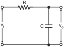
Single-section RC low-pass circuit
Figure below shows the basic RC low-pass circuit comprising a single-section RC circuit. As we can see from the figure the output is taken across the capacitor.
Single-section RC low-pass circuit
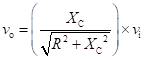
The output voltage falls with increase in frequency (refer to figure below) as the output is taken across the capacitor and the reactance of a capacitor is inversely proportional to the frequency. The output voltage is given by
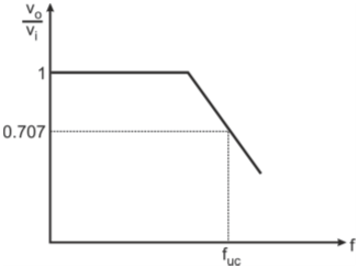
Frequency response of a RC low-pass circuit
Therefore, the RC network behaves as a low-pass circuit.
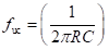
The upper 3 dB cut-off frequency is the frequency at which output amplitude is 0.707 times (or 3 dB below) the nominal maximum amplitude. The nominal maximum output amplitude is same as the input amplitude; therefore, the ratio (vo/vi) equals 0.707 at 3 dB cut-off frequency. The ratio (vo/vi) becomes 0.707 when the resistance (R) equals capacitive reactance (Xc). Therefore, the cut-off frequency (fuc) is given by
Refer to figure below.
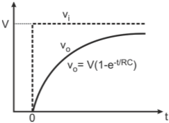
Step response of low-pass circuit
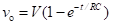
For a step input (vi), the output voltage (vo), which is also voltage across C, rises exponentially towards the final value of V with a time constant (RC). The output voltage (vo) is given by
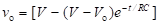
This expression is valid only when the capacitor is initially fully discharged. If the capacitor were initially charged to a voltage Vo, less than V, then the exponential charging equation would be
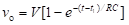
If this input step occurs at time t = t1, then the following equation represents the charging process:
Refer to figure below.
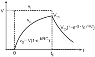
Pulse response of low-pass circuit
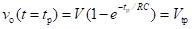
For a pulse input, output (vo) during the high time of the pulse is given by

At t = tp, the amplitude of the output voltage is given by
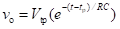
The output (vo) during the low time of the pulse is given by
The quality with which the network reproduces fast transitions is expressed by the magnitude of the rise time (tr) which is the time taken by the output to change from 10% to 90% of the impressed transition or step. Rise time for a low-pass RC filter is given by

The relationship between the upper 3 dB cut-off frequency (fuc) and the rise time (tr) is given by

This expression indicates that higher the upper 3 dB cut-off frequency, smaller is the rise time. Therefore, for faithful reproduction of fast transitions, fuc should be as high as possible.
For an integrator circuit, the output voltage vo should be integral of the input voltage (vi), that is,

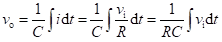
Where, k is a constant In the given RC circuit, if the product RC is much larger than the time period (T) of the applied input, the capacitor voltage (or the output voltage in the present case) would change by only a very small amount as the input goes through a complete cycle. In such a case, we can assume that whole of input voltage (vi) appears across the resistor (R) only. As a result current (i) can be expressed as

The output voltage (vo) across the capacitor is given by
Therefore, output voltage (vo) is integral of input voltage (vi) provided that the time constant is much larger than the time period of the input signal, that is, RC >>T. In fact, if RC 15T integration is near ideal.
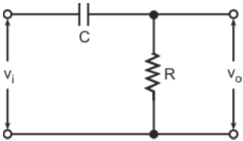
Figure below shows the circuit of a single-section basic RC high-pass circuit.
Single section RC high-pass circuitSingle section RC high-pass circuit
The output voltage (vo) is given by
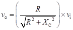
Since the reactance of a capacitor is inversely proportional to the frequency, it would increase with decrease in frequency. Therefore, the output voltage falls with decrease in frequency of the input waveform. Therefore, the circuit behaves as a high-pass filter circuit (refer to figure below).
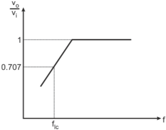
Frequency response of RC high-pass circuit
The frequency where the ratio vo/vi falls to 0.707 of its maximum value is known as the lower 3 dB cut-off frequency. At the lower 3 dB cut-off frequency (flc),
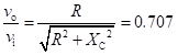
Therefore at flc, The lower 3 dB cut-off frequency is given by

The lower 3 dB cut-off frequency affects the low-frequency response due to the high-pass nature of the circuit. Smaller the lower 3 dB cut-off frequency, less severe is its effect on the flatter portions of the waveform. The effect of different lower 3 dB cut-off frequencies in a high-pass RC circuit for a pulsed waveform input is depicted in figure below.

Effect of lower 3 dB cut-off frequency on pulsed waveform input
A differentiator circuit is the one in which the output response is proportional to the differential or the slope of the input signal. In the RC high-pass circuit of Q8, if the time constant (RC) is much smaller than the input waveform time period, then we can assume that whole of input (vi) appears (C) only as the input goes through one complete cycle. The current (i) flowing in the circuit is given by

The output voltage (vo) is given by

Therefore, the RC high-pass circuit behaves as a differentiator when the time constant (RC) is much smaller than the input waveform time period.
For a simple differentiator circuit (RL or RC),

Where, is the time constant which is equal to RC (for RC circuit) or L/R (for RL circuit)